I2C总线是一种简单、双向二线制同步串行总线。SDA(串行数据线)和SCL(串行时钟线)都是双向I/O线,接口电路为开漏输出。需通过上拉电阻接电源VCC.当总线空闲时。两根线都是高电平,连接总线的外同器件都是CMOS器件,输出级也是开漏电路。
MicroPython
我们以OLED屏幕的通信为例。
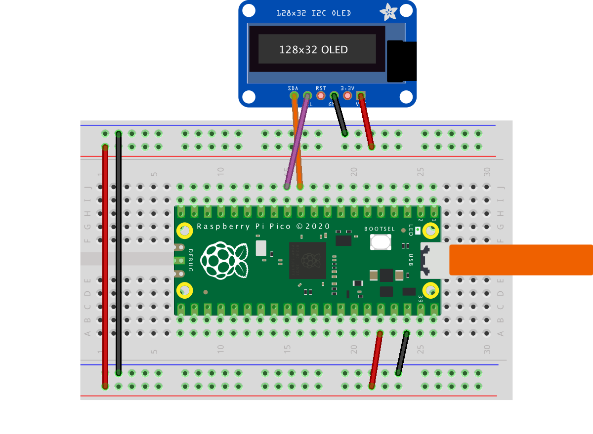
from machine import I2C, ADC
from sh1106 import SH1106_I2C
import framebuf


WIDTH  = 128                                            # oled display width
HEIGHT = 128                                            # oled display height

i2c = I2C(0)                                            # Init I2C using I2C0 defaults, SCL=Pin(GP9), SDA=Pin(GP8), freq=400000
print("I2C Address      : "+hex(i2c.scan()[0]).upper()) # Display device address
print("I2C Configuration: "+str(i2c))                   # Display I2C config


oled = SH1106_I2C(WIDTH, HEIGHT, i2c)                  # Init oled display

# Raspberry Pi logo as 32x32 bytearray
buffer = bytearray(b"\x00\x00\x00\x00\x00\x00\x00\x00\x00\x00\x00\x00\x00|?\x00\x01\x86@\x80\x01\x01\x80\x80\x01\x11\x88\x80\x01\x05\xa0\x80\x00\x83\xc1\x00\x00C\xe3\x00\x00~\xfc\x00\x00L'\x00\x00\x9c\x11\x00\x00\xbf\xfd\x00\x00\xe1\x87\x00\x01\xc1\x83\x80\x02A\x82@\x02A\x82@\x02\xc1\xc2@\x02\xf6>\xc0\x01\xfc=\x80\x01\x18\x18\x80\x01\x88\x10\x80\x00\x8c!\x00\x00\x87\xf1\x00\x00\x7f\xf6\x00\x008\x1c\x00\x00\x0c \x00\x00\x03\xc0\x00\x00\x00\x00\x00\x00\x00\x00\x00\x00\x00\x00\x00")

# Load the raspberry pi logo into the framebuffer (the image is 32x32)
fb = framebuf.FrameBuffer(buffer, 32, 32, framebuf.MONO_HLSB)

# Clear the oled display in case it has junk on it.
oled.fill(0)

# Blit the image from the framebuffer to the oled display
oled.blit(fb, 96, 0)

# Add some text
oled.text("Raspberry Pi",5,5)
oled.text("Pico",5,15)

# Finally update the oled display so the image & text is displayed
oled.show()
C/C++
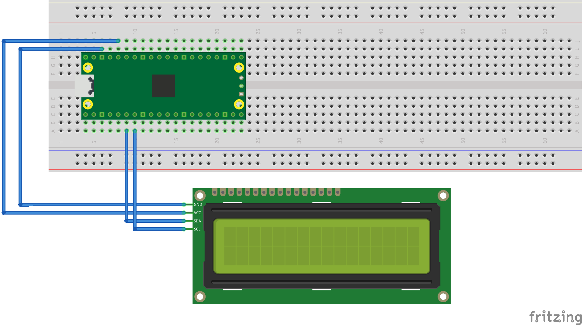
我们以LCD1602为例。
#include <stdio.h>
#include <string.h>
#include "pico/stdlib.h"
#include "hardware/i2c.h"
#include "pico/binary_info.h"

/* Example code to drive a 16x2 LCD panel via a I2C bridge chip (e.g. PCF8574)
   NOTE: The panel must be capable of being driven at 3.3v NOT 5v. The Pico
   GPIO (and therefor I2C) cannot be used at 5v.
   You will need to use a level shifter on the I2C lines if you want to run the
   board at 5v.
   Connections on Raspberry Pi Pico board, other boards may vary.
   GPIO 4 (pin 6)-> SDA on LCD bridge board
   GPIO 5 (pin 7)-> SCL on LCD bridge board
   3.3v (pin 36) -> VCC on LCD bridge board
   GND (pin 38)  -> GND on LCD bridge board
*/
// commands
const int LCD_CLEARDISPLAY = 0x01;
const int LCD_RETURNHOME = 0x02;
const int LCD_ENTRYMODESET = 0x04;
const int LCD_DISPLAYCONTROL = 0x08;
const int LCD_CURSORSHIFT = 0x10;
const int LCD_FUNCTIONSET = 0x20;
const int LCD_SETCGRAMADDR = 0x40;
const int LCD_SETDDRAMADDR = 0x80;

// flags for display entry mode
const int LCD_ENTRYSHIFTINCREMENT = 0x01;
const int LCD_ENTRYLEFT = 0x02;

// flags for display and cursor control
const int LCD_BLINKON = 0x01;
const int LCD_CURSORON = 0x02;
const int LCD_DISPLAYON = 0x04;

// flags for display and cursor shift
const int LCD_MOVERIGHT = 0x04;
const int LCD_DISPLAYMOVE = 0x08;

// flags for function set
const int LCD_5x10DOTS = 0x04;
const int LCD_2LINE = 0x08;
const int LCD_8BITMODE = 0x10;

// flag for backlight control
const int LCD_BACKLIGHT = 0x08;

const int LCD_ENABLE_BIT = 0x04;

#define I2C_PORT i2c0
// By default these LCD display drivers are on bus address 0x27
static int addr = 0x27;

// Modes for lcd_send_byte
#define LCD_CHARACTER  1
#define LCD_COMMAND    0

#define MAX_LINES      2
#define MAX_CHARS      16

/* Quick helper function for single byte transfers */
void i2c_write_byte(uint8_t val) {
    i2c_write_blocking(I2C_PORT, addr, &val, 1, false);
}

void lcd_toggle_enable(uint8_t val) {
    // Toggle enable pin on LCD display
    // We cannot do this too quickly or things don't work
#define DELAY_US 600
    sleep_us(DELAY_US);
    i2c_write_byte(val | LCD_ENABLE_BIT);
    sleep_us(DELAY_US);
    i2c_write_byte(val & ~LCD_ENABLE_BIT);
    sleep_us(DELAY_US);
}

// The display is sent a byte as two separate nibble transfers
void lcd_send_byte(uint8_t val, int mode) {
    uint8_t high = mode | (val & 0xF0) | LCD_BACKLIGHT;
    uint8_t low = mode | ((val << 4) & 0xF0) | LCD_BACKLIGHT;

    i2c_write_byte(high);
    lcd_toggle_enable(high);
    i2c_write_byte(low);
    lcd_toggle_enable(low);
}

void lcd_clear(void) {
    lcd_send_byte(LCD_CLEARDISPLAY, LCD_COMMAND);
}

// go to location on LCD
void lcd_set_cursor(int line, int position) {
    int val = (line == 0) ? 0x80 + position : 0xC0 + position;
    lcd_send_byte(val, LCD_COMMAND);
}

static void inline lcd_char(char val) {
    lcd_send_byte(val, LCD_CHARACTER);
}

void lcd_string(const char *s) {
    while (*s) {
        lcd_char(*s++);
    }
}

void lcd_init() {
    lcd_send_byte(0x03, LCD_COMMAND);
    lcd_send_byte(0x03, LCD_COMMAND);
    lcd_send_byte(0x03, LCD_COMMAND);
    lcd_send_byte(0x02, LCD_COMMAND);

    lcd_send_byte(LCD_ENTRYMODESET | LCD_ENTRYLEFT, LCD_COMMAND);
    lcd_send_byte(LCD_FUNCTIONSET | LCD_2LINE, LCD_COMMAND);
    lcd_send_byte(LCD_DISPLAYCONTROL | LCD_DISPLAYON, LCD_COMMAND);
    lcd_clear();
}

int main() {
    // This example will use I2C0 on GPIO4 (SDA) and GPIO5 (SCL)
    i2c_init(I2C_PORT, 100 * 1000);
    gpio_set_function(4, GPIO_FUNC_I2C);
    gpio_set_function(5, GPIO_FUNC_I2C);
    gpio_pull_up(4);
    gpio_pull_up(5);
    // Make the I2C pins available to picotool
    bi_decl( bi_2pins_with_func(4, 5, GPIO_FUNC_I2C));

    lcd_init();

    static uint8_t *message[] =
            {
                    "RP2040 by", "Raspberry Pi",
                    "A brand new", "microcontroller",
                    "Twin core M0", "Full C SDK",
                    "More power in", "your product",
                    "More beans", "than Heinz!"
            };

    while (1) {
        for (int m = 0; m < sizeof(message) / sizeof(message[0]); m += MAX_LINES) {
            for (int line = 0; line < MAX_LINES; line++) {
                lcd_set_cursor(line, (MAX_CHARS / 2) - strlen(message[m + line]) / 2);
                lcd_string(message[m + line]);
            }
            sleep_ms(2000);
            lcd_clear();
        }
    }

    return 0;
}
CMakeList.txt:
add_executable(lcd_1602_i2c
        lcd_1602_i2c.c
        )

# Pull in our (to be renamed) simple get you started dependencies
target_link_libraries(lcd_1602_i2c pico_stdlib hardware_i2c)

# create map/bin/hex file etc.
pico_add_extra_outputs(lcd_1602_i2c)

# add url via pico_set_program_url
example_auto_set_url(lcd_1602_i2c)